Frequency (Octave) Mod for the TI99....
This mod will allow you to lower the frequency range of the TI99 sound chip by two full octaves. It was suggested by Mark Wills with input by Jens-Einke (I hope the spelling is correct.) It turns out to be fairly easy to do and doesn't seem to have any adverse effects on the console. Having said this, undertake at your own risk. The circuit is essentially a 74LS74 chip used to divide the clock signal to the 9919. After the logic chip the clock rate is one forth what it normally is and since the 9919 generates sound based on this clock frequency the outputted sound frequencies are four times lower. No recalculation of musical notes are needed other than frequency modifications. Below are a couple of pictures of a point to point board I made up as well as a "Hook Up Diagram" showing the needed connections. Lastly is a video showing the effects of the mod.
The parts needed are...
1-74LS74 or equivalent
2- rows of 8 pin SIPS to plug into the MOBO socket
Some hook up wire and a small piece of perf board.
The 9919 can be pulled from it's socket and reused on the perf board.
The top case will need to have a bit of plastic cut from the interior. There is a leg that may interfere with the board placement. A hacksaw blade made quick work of this.
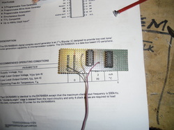
Board completed uninstalled

This is the board complete and ready to plug in. The piece of ribbon cable connects to a SPDT switch located on the console. This switch allows selecting between normal sound and lowered sound. Notice the offset of the perf board at the lower left. A small notch must be cut in the board to allow it to fit around the GROM connector.
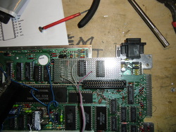
Board plugged in and ready to go

Here is the MOBO with the board plugged in to the original 9919 socket. It is a snug fit to match the pins on the bottom of the board and to wrap around the GROM connector.
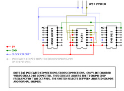
"Hook Up Diagram"

This is a MS Paint file showing the board hookups. what it does not show is the fact that below the 9919 socket picture you will need some pins. I chose to use normal size Jumper pins as they are a bit beefier than machine pins and fit the dual wipe socket better. Please note the orientation of the IC's. You are building this circuit upside down. Below is a down loadable copy of the file.
| ti99_freq_mod.bmp | |
| File Size: | 675 kb |
| File Type: | bmp |